

A GNSS Simulation System for Real Time Tracking within Tunnels
Transport for NSW Specification TS912 calls out Location Service requirements within Traffic Management and Control System (TMCS) for Motorways, including within Tunnels. The requirement calls for industry standard technologies that are commonly available. To be able to use a vehicle standard GNSS receiver, used in the vehicles Satellite Navigation system, infrastructure needs to be installed inside the tunnel and simulate the same signals and data so that the vehicles GNSS receiver decodes the signals and data as if it had open sky reception from the satellites in view above the tunnel.
A GNSS (in Australia this consists of the GPS, GLONASS, BEIDOU and QZSS satellite constellations) receiver calculates its position by calculating the time that a signal takes to travel from a single satellite to the receivers GNSS antenna. By knowing the travel time then the receiver can calculate the distance, and by knowing the position of the satellite above the earth, it can calculate a relative position on the earths surface. With 3 satellite being tracked, the receiver can calculate a Longitude and Latitude position. With 4 satellites being tracked, the receiver can also calculate an altitude position. Normal GNSS receivers that are used in vehicle navigation systems, can provide an accuracy to 2m with clear open sky.
There are 4 critical types of data required from the satellites for a GNSS receiver to accurately calculate its position. This is:
- Almanac – has information about the satellites orbit and status
- Ephemeris – provides the satellite position
- Pseudo Random Code – is used to calculate the travel time from the satellite
- UTC (Universal Time Code)
So to be able to have the GNSS receiver in the tunnel calculate its position, then it needs to be able to receive satellite signals as if it had open sky reception. Most important is that the satellite data radiating in the tunnel is the same data in real time to an open sky reception.
Now you could ask, why don’t we use an external antenna then just radiate that in the tunnel. The answer to this is quite simple, your vehicle GNSS receiver will only calculate one position throughout the length of the tunnel, and that will be the location of the external antenna. The altitude calculated will be entirely wrong, especially where you have tunnel tubes running on top of another.
What is required is simulated satellite signals that take into account the locations within the tunnel. This is achieved by using a series of radiating antennas in the tunnel ceiling. The signal from each of these antennas is relative to the precise position (longitude, latitude and altitude) of each antenna. The vehicle GNSS receiver will then calculate its position within the tunnel to the position of the radiating antenna.
The positional accuracy of the vehicle will depend on the vehicles speed and its GNSS reporting frequency. If we look at a vehicle travelling through the tunnel at 60 kph, then it will travel 1 km per minute or 20m per second. In general, an AVL or Telematics system will report between 10 seconds and 30 seconds, or a distance of 100 m. However, in an emergency situation, it will be the vehicle stationary position that will be important so the spacing of the radiating antennas will determine the vehicle reported positional accuracy.
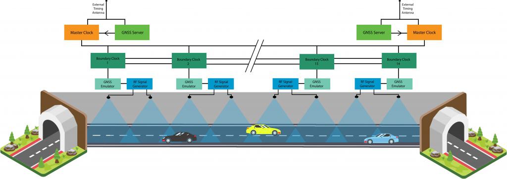
In order to simulate the GNSS signals at each radiating antenna, the time clock at the simulator has to be accurate to within a few nanoseconds of UTC. To achieve this level of accuracy to each and every radiating antenna, we have to start with a time server that can output the Precision Time Protocol (PTP), as well as a synchronisation signal that is locked to UTC.
To provide the current Almanac & Ephemeris data, a PTP server is required to feed this data to the individual simulators. The PTP servers external GNSS antenna must have clear view of the sky with no RF interference. The accuracy is critical and needs to be within 15nSec for the simulators to be precise.
The PTP server feeds the satellite data to a computer running a simulation software. The software is configured for the tunnel, taking into account the many factors required for accurate simulation. The software then outputs the specific simulator parameters and is fed to the dedicated simulators. The simulators take these settings and the timing signals to then generate the satellite RF signals for each of the radiating antennas mounted in the ceiling of the tunnel. Each antenna must be precisely located so that its position and elevation are accurately known and used by the simulation system.
To a vehicle travelling through the tunnel, their tracking unit will see the same Almanac and Ephemeris data as if they were under open sky. As they pass from one antenna field to another their position will be updated.
Step Global has been providing precision timing and asset management systems for almost 2 decades. Step Global takes on full design authority, product supply and ongoing maintenance and service for the deployment of the NoSky SatNav GNSS tunnel positioning system.
For more information contact the Step Global team at sales@stepglobal.com or 03 9551 7334.